What Is an Oil Filled Transformer and How Does It Work?

An Oil Filled Transformer transfers electrical energy between voltage levels while managing heat and insulation inside a sealed steel tank. Its laminated steel core guides magnetic flux, while copper or aluminum windings carry the current. Mineral oil or biodegradable ester fluid surrounds these active parts. The fluid strengthens insulation and moves heat toward the tank walls, radiators, or cooling fans. Small details matter. A blocked radiator can quietly raise winding temperature. Moisture can weaken insulation. A damaged bushing can create a serious failure point.

This technology remains important as electricity networks expand and aging assets face heavier loads. The International Energy Agency’s Electricity Grids and Secure Energy Transitions report estimates that over 80 million kilometers of grids must be added or replaced globally by 2040. It also projects annual grid investment will need to exceed 600 billion dollars by 2030. Transformers support this expansion at substations, industrial facilities, renewable-energy sites, and distribution networks. IEC 60076 defines key requirements for transformer design, testing, insulation, temperature rise, and operation. IEEE C57 standards provide additional guidance for transformer ratings, performance, and safety practices.

However, oil cooling is not a perfect solution. Oil quality changes with heat, oxygen, moisture, and operating age. Regular dissolved-gas analysis can reveal overheating, arcing, or insulation damage before visible failure occurs. Conservators, breathers, pressure-relief devices, and temperature indicators also require practical inspection. This article explains what an Oil Filled Transformer is, how its cooling and insulation systems work, and why maintenance decisions influence reliability, efficiency, and service life. Real equipment is less forgiving than a diagram.
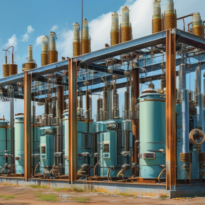
What Is an Oil Filled Transformer and How Does It Work?

What Is an Oil-Filled Transformer?

An oil-filled transformer is an electrical device that changes voltage through electromagnetic induction. Its core and windings sit inside a sealed or conservator-equipped tank. Insulating oil surrounds these energized parts. The oil separates conductors and carries heat toward the tank walls, radiators, or cooling fins. This design supports reliable operation in substations, industrial facilities, and utility networks.

When alternating current enters the primary winding, it creates a changing magnetic field in the laminated steel core. That field induces voltage in the secondary winding. The winding ratio determines whether the transformer raises or lowers voltage.

During operation, oil temperature can increase noticeably under heavy load. Engineers check oil level, moisture, dissolved gases, bushing condition, and unusual sounds during scheduled inspections. The simple explanation is useful, but incomplete. Oil quality and heat removal often decide service life.

Tips: Keep the tank clean and inspect it for leaks, corrosion, or damaged seals. Use temperature readings from actual operating conditions, not guesses. Oil sampling should follow qualified procedures and laboratory guidance. A small leak may look harmless, yet it can reduce insulation performance over time. Maintenance records also matter. They reveal gradual changes that a single inspection might miss. Ventilation around radiators must remain clear. Some installations require extra review after overloads, faults, or sudden temperature changes.

What Are the Main Components of an Oil-Filled Transformer?

What Is an Oil-Filled Transformer and How Does It Work?

An oil-filled transformer transfers electrical energy between circuits through electromagnetic induction. Its main components work together inside a sealed or conservator-type tank. The laminated steel core guides magnetic flux, while copper or aluminum windings carry high- and low-voltage currents. Mineral or ester-based insulating liquid surrounds these parts. It removes heat and strengthens insulation between energized conductors.

The tank contains radiators, bushings, a tap changer, and protection devices. Radiators release heat into surrounding air. Bushings guide conductors safely through the tank wall. A tap changer adjusts the output voltage when supply conditions change. The conservator allows liquid expansion during heating, while a breather controls moisture entering the system. A pressure-relief device reduces dangerous internal pressure. CIGRE’s Transformer Reliability Survey highlights bushings, tap changers, and insulation systems as important failure contributors. The U.S. Department of Energy’s technical analysis estimated that distribution transformers consume about 61 billion kilowatt-hours annually. That figure shows why component condition matters.

Tips: Check oil temperature, dissolved gases, leaks, and bushing surfaces during inspections. IEC 60076-1 supports routine transformer testing, but no single measurement proves transformer health. A clean exterior can hide aging insulation. I have seen maintenance plans overvalue oil tests and overlook loose connections. That is a weakness worth reviewing. Record load history, unusual noise, and seasonal temperature changes. Small clues often explain larger failures.

How Does an Oil-Filled Transformer Work Step by Step?

An oil-filled transformer transfers electrical energy between circuits through electromagnetic induction. Its steel core and copper windings sit inside a tank filled with insulating oil. The oil provides insulation and carries heat away from the windings. This combination supports reliable operation under changing electrical loads.

The process starts when alternating current enters the primary winding. The current creates a changing magnetic field inside the laminated steel core. That magnetic field crosses the secondary winding and induces a new voltage. The turns ratio determines whether the transformer increases or reduces voltage. No direct electrical connection exists between the two windings. That separation matters.

As current flows, the windings produce heat. The oil absorbs this heat and circulates toward cooler tank walls. Cooler oil then moves back toward the windings. Some transformers use radiators to release heat more efficiently. A conservator tank may allow oil expansion during hot operation. A breather helps limit moisture entering the system. Moisture is a quiet problem. It can weaken insulation and accelerate aging. Technicians check oil level, temperature, leaks, and dissolved gases during maintenance. Dark oil does not always prove failure, yet ignoring unusual odor or bubbles is poor practice. In real service, load changes, ambient heat, and maintenance history can complicate the expected sequence. The transformer may work normally while its insulation slowly deteriorates. That hidden condition deserves careful testing.

How Does Transformer Oil Provide Cooling and Insulation?

An oil-filled transformer uses insulating liquid around its windings and magnetic core. When energized, copper windings produce heat through electrical resistance. The core also warms because of magnetic losses. Transformer oil performs two essential jobs: cooling and insulation.

As the oil warms, it becomes less dense and rises inside the tank. Cooler oil moves downward to replace it. This natural circulation is called thermosiphon cooling. Larger transformers may use pumps and external radiators to move heat faster. The process is quiet, but continuous. Heat then travels from the oil to the tank walls, radiators, and surrounding air.

Oil also fills small spaces between energized components. This reduces the risk of electrical arcing and helps maintain stable voltage isolation. However, the protection is not permanent. Water, dust, oxygen, and excessive heat can weaken the oil’s dielectric strength. Sludge may also form and restrict circulation. A practical inspection should check oil level, temperature, appearance, acidity, moisture, and breakdown voltage. Sampling must use clean equipment because a tiny amount of contamination can distort test results. The system sounds simple, yet its reliability depends on details. A small leak, blocked radiator, or aging seal can gradually reduce cooling performance. Regular testing provides evidence before these problems become serious.

What Are the Common Applications and Maintenance Needs?

An oil-filled transformer uses insulating liquid to transfer heat away from energized windings and the magnetic core. The oil also strengthens electrical insulation between internal components. As the transformer operates, heated oil rises, cools near the tank walls or radiators, and circulates again. This natural movement is called thermosiphon cooling.

These transformers serve utility substations, commercial buildings, renewable-energy sites, and heavy industrial facilities. They are useful where stable voltage conversion and continuous operation matter. A substation transformer may quietly support an entire neighborhood, while a smaller unit can supply motors and lighting in a factory. Maintenance should include visual checks for oil leaks, damaged bushings, unusual noise, rust, and abnormal temperature readings. Technicians often test oil dielectric strength, moisture, acidity, and dissolved gases. These results can reveal insulation aging before a failure occurs. A clean tank does not prove healthy internal insulation. That assumption deserves more caution.

Tips: Record readings consistently. Compare trends, not isolated numbers. Check the conservator level, breather condition, radiator valves, and grounding connections. Keep inspection areas dry and unobstructed. Maintenance intervals should follow the transformer’s duty, environment, loading, and manufacturer guidance. A schedule helps, but it is not infallible. Only qualified personnel should inspect energized equipment or perform electrical testing under applicable safety procedures.

What Is an Oil Filled Transformer and How Does It Work? – Common Applications and Maintenance Needs

Data Dimension Typical Information Practical Significance
Definition An oil-filled transformer is a static electrical device that uses insulating liquid to provide electrical insulation and remove heat from its windings and core. It enables efficient voltage transformation while supporting insulation performance and thermal control.
Basic Operating Principle Alternating current in the primary winding creates a changing magnetic flux in the core. The flux induces a voltage in the secondary winding through electromagnetic induction. The turns ratio determines whether the transformer steps voltage up or down while maintaining the same frequency.
Main Internal Components Magnetic core, high- and low-voltage windings, insulating liquid, tank, bushings, tap changer, radiators or cooling fins, conservator tank, and protective devices. Each component contributes to voltage transformation, insulation, heat dissipation, connection, or protection.
Insulating Liquid Mineral insulating oil is widely used. Ester-based insulating liquids may also be selected where higher fire safety, biodegradability, or environmental performance is required. The liquid must provide adequate dielectric strength, thermal conductivity, chemical stability, and compatibility with internal materials.
Cooling Method Small and medium units commonly use natural oil circulation and natural air cooling. Larger units may use directed oil flow, fans, pumps, or combinations of natural and forced cooling. Cooling capacity limits the transformer’s allowable continuous load and helps control insulation aging.
Voltage Conversion Distribution transformers commonly reduce medium voltage to utilization voltage. Power transformers may increase or decrease voltage between transmission and subtransmission networks. The required voltage ratio depends on the electrical network and connected equipment.
Common Applications Utility distribution substations, industrial facilities, commercial buildings, renewable-energy collection systems, traction power systems, and generation or transmission substations. Oil-filled designs are suitable for outdoor and high-capacity installations where efficient cooling and long service life are important.
Typical Rating Range Ratings range from small distribution units of several tens or hundreds of kVA to large power transformers rated in tens or hundreds of MVA. Actual ratings depend on voltage class, cooling system, installation conditions, load profile, and applicable standards.
Key Advantages High thermal efficiency, effective insulation, strong overload capability when properly designed, suitability for high ratings, and generally long operating life. These characteristics make oil-filled transformers practical for demanding outdoor and utility applications.
Important Limitations Mineral oil is combustible, leaks can affect the environment, and the equipment requires containment, fire-safety planning, and periodic oil-condition monitoring. Site design may require bunds, oil-collection systems, fire barriers, alarms, or alternative insulating liquids.
Routine Visual Inspection Check for oil leaks, tank corrosion, damaged bushings, abnormal noise, unusual vibration, blocked radiators, loose connections, and signs of overheating. Early detection can prevent insulation damage, reduced efficiency, unplanned outages, and safety incidents.
Insulating Liquid Tests Common tests include dielectric breakdown voltage, moisture content, acidity, interfacial tension, color, resistivity, and dissolved gas analysis. Results help identify moisture, oxidation, overheating, arcing, partial discharge, or other developing faults.
Dissolved Gas Analysis DGA evaluates gases such as hydrogen, methane, ethane, ethylene, acetylene, carbon monoxide, and carbon dioxide dissolved in the insulating liquid. Gas patterns can indicate thermal faults, electrical discharges, paper insulation overheating, or abnormal aging.
Electrical Condition Tests Testing may include insulation resistance, winding resistance, turns ratio, excitation current, power factor or dissipation factor, and protective-device checks. Trend comparisons help identify winding problems, insulation deterioration, tap-changer issues, or connection defects.
Temperature Monitoring Monitor top-liquid temperature, winding temperature where available, ambient temperature, and cooling-equipment operation. Excessive temperature accelerates paper insulation aging and may indicate overload, restricted cooling, or an internal fault.
Maintenance Frequency Visual checks are often performed regularly, while oil sampling and electrical testing are scheduled according to operating conditions, criticality, manufacturer guidance, and local standards. There is no universal interval; heavily loaded, older, or critical transformers generally need more frequent assessment.
Typical Protective Devices Common devices include pressure-relief equipment, oil-level indicators, temperature indicators, sudden-pressure or gas-actuated relays, surge arresters, and overcurrent protection. Protection limits damage and provides alarms or trip signals when abnormal electrical, thermal, or mechanical conditions occur.
Service-Life Factors Load level, hot-spot temperature, moisture, oxygen exposure, contamination, short-circuit forces, switching events, and maintenance quality influence service life. Managing thermal stress and keeping the insulation system dry and clean can significantly slow aging.